Home Security System Circuit Diagram
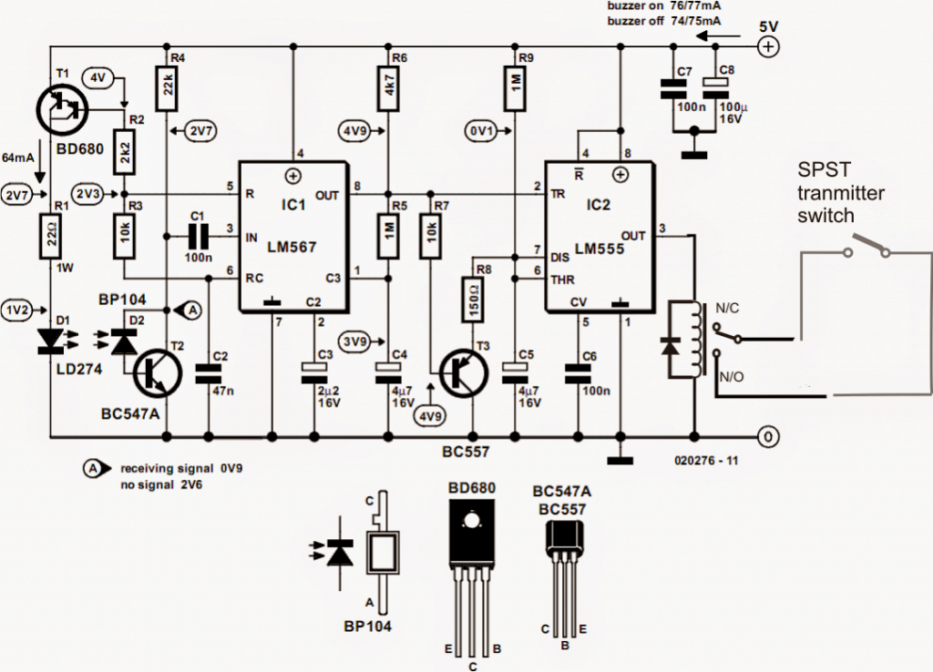
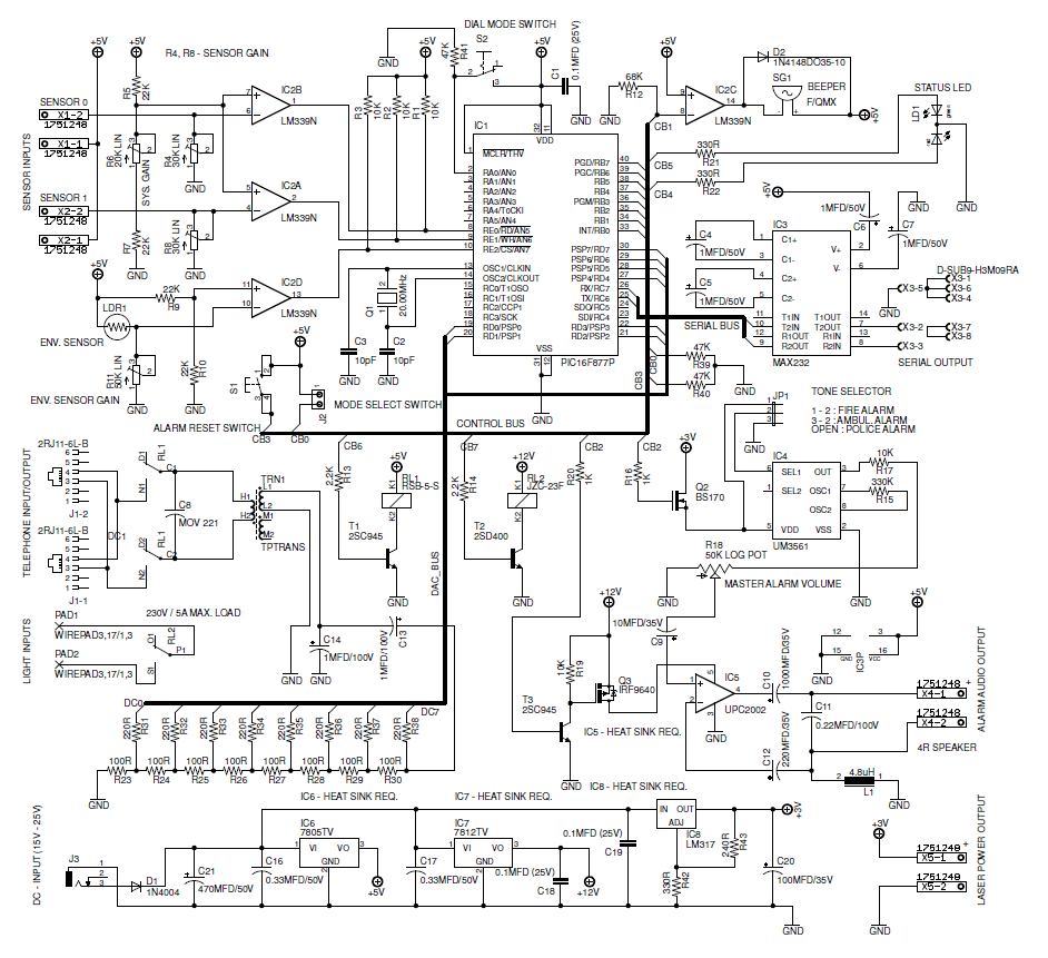
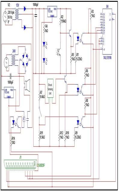
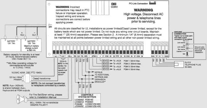
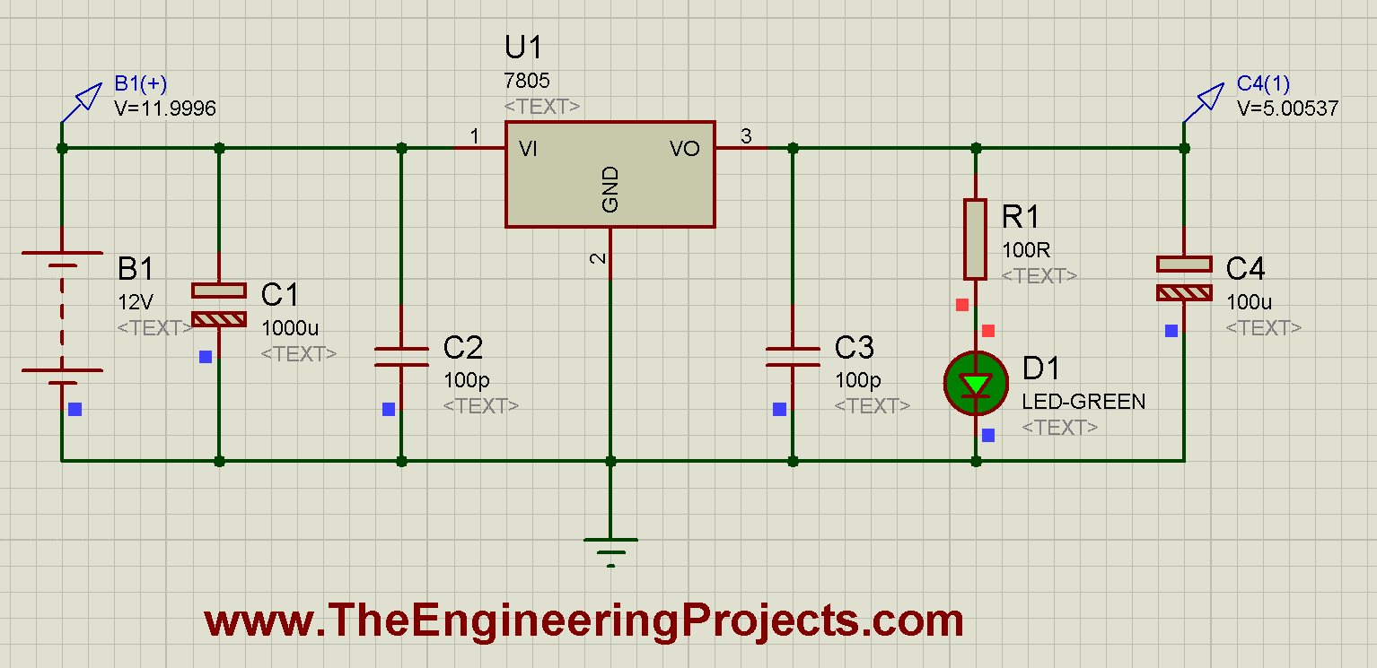
Home security system circuit diagram. It shows the parts of the circuit as streamlined shapes and also the power and also signal connections between the gadgets. Home Security System Wiring Diagram Posted by Margaret Byrd Posted on February 9 2018 How to install a home security system dsc burglar alarm wiring the y guide motion detector for securing doors aa 6072 circuit diagram private sector car. Resistors are the passive device with two terminals.
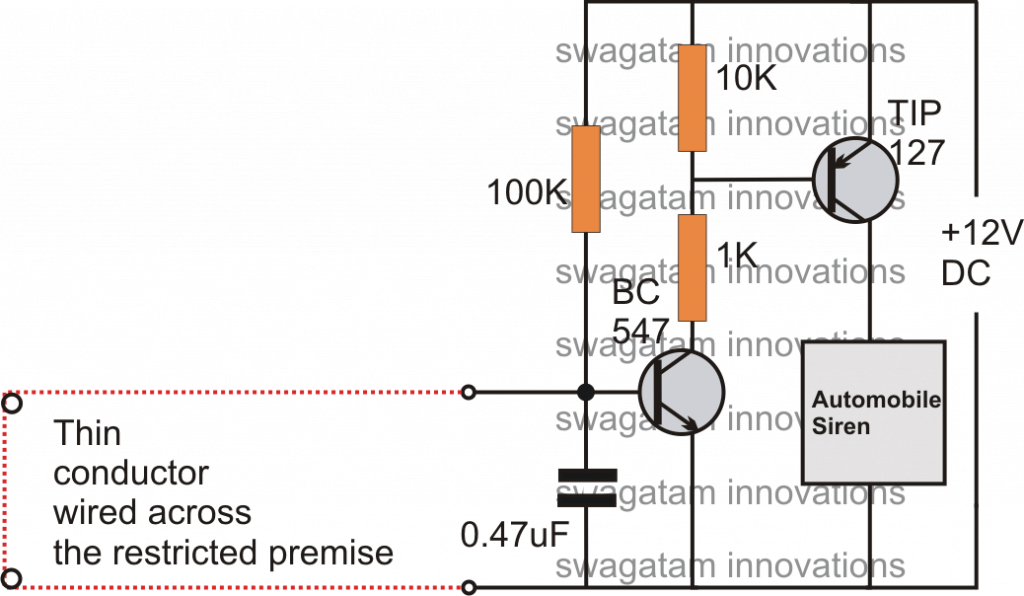
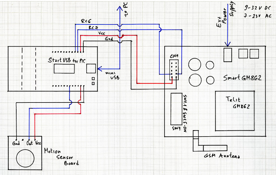
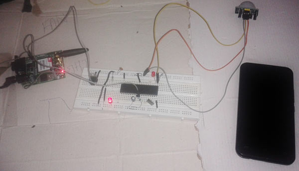
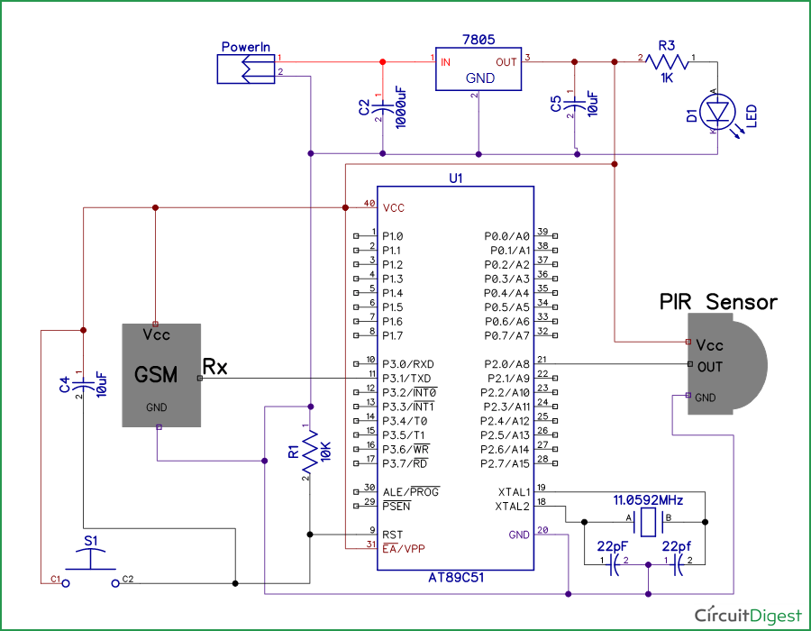
Circuit diagram of Home security system using PIR. Drill Holes in the Housing 3. There are many security systems use a closed loop of wires and switches arranged so that whenever a door or window is opened the loop will be broken and the alarm will sound.
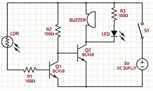
Before using this security system make sure that loops shown in Fig. This is connected to any of the digital IO pins of the Arduino. In this laser security alarm circuit we have used LM358 Dual Comparator IC for comparing voltages coming from LDR.
2 shows the proposed wiring diagram for the loops around the premises. Variety of home security system wiring diagram. Here the circuit diagram of safer security system alarm.
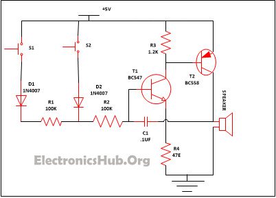
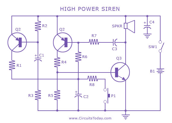
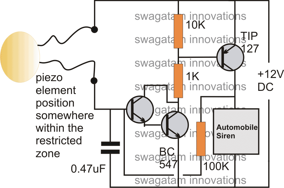
By Margaret Byrd December 19 2017. Here is the circuit diagram of simple multitone alarm. It reveals the elements of the circuit as streamlined forms as well as the power as well as signal connections in between the devices.
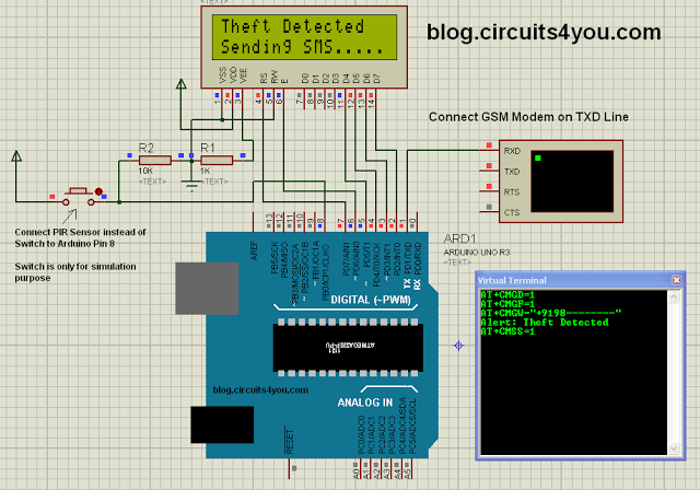
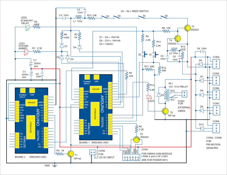
1 shows circuit diagram of the Arduino based GSM home security system. Home Security System Wiring Diagram Collection. As the project is based on an Arduino the connection is pretty simple.
The full circuit diagram of Home security alarm Relay1 Switch1 onOff Relay2 Daylight. R1 R2 100K 2.
Connecting LCD to Arduino 3.
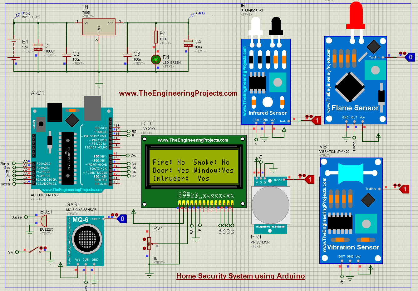
The first one is the IR transmitter and receiver module which works for the safety of doors at night or in case we are out of the home. T1T2 Darlington is switshed off In darkness T1T2 Darlignton is switched on 7. The two op amps inside the MC 1458 are used to produce square and triangular waves. Laser Security System Circuit Diagram and Explanation. An obvious problem is that someone can tamper with the system short out the loop and later on come back and burglarize the premises without sounding the alarm. The digital security system circuit. It works off a 12V power supply connected across CON2. By Margaret Byrd December 19 2017. Variety of home security system wiring diagram.
Build an iButton electronic lock based around a AT91C2051 microcontroller includes ASM source code Alarms. A wiring diagram is a simplified standard pictorial representation of an electric circuit. T1T2 Darlington is switshed off In darkness T1T2 Darlignton is switched on 7. When the IR sensors are interrupted a buzzer if turned on indicating someone is entered into house. Connecting LCD to Arduino 3. 1 shows circuit diagram of the Arduino based GSM home security system. The first one is the IR transmitter and receiver module which works for the safety of doors at night or in case we are out of the home.














Post a Comment for "Home Security System Circuit Diagram"